Equipment
Truck Checks: Diagnosing starter condition
During a recent fourth-year heavy equipment technician class we set out to determine whether an oscilloscope can be used to diagnose starter condition.
February 25, 2009
By Don Henry
 |
|
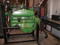
| Photo 1: 619 CID engine Photos courtesy Don Henry |
|
 |
|
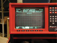
| Photo 2: Pattern of a normal starter. |
|
 |
|
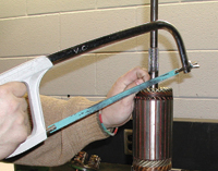
| Photo 3: Cutting armature windings. |
|
 |
|
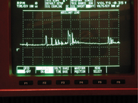
| Photo 4: Abnormal pattern. |
During a recent fourth-year heavy equipment technician class we set out to determine whether an oscilloscope can be used to diagnose starter condition.
A starter takes 12 volts of DC (direct current) and produces a pulsed DC current. How efficiently it does this is an indication of the condition of the brushes, field windings and armature windings.
As a starter begins to wear down, its brushes no longer contact the commutator on the armature, or the armature windings can open. This often happens at the solder that connects the windings to the commutator. This solder can melt because of long cranking periods or starter overload. Ether condition creates an open to current to flow.
The engine chosen for this test was an agriculture engine of 619 CID (cubic inch displacement) with a common 40 MT Delco starter (see photo 1). A well-charged 1200 CCA battery was used to crank this engine in a warm shop with 15W-40-weight engine oil. The test results of three cranks were an average draw of 590 amps and an average cranking speed of 260 rpm. The rpm was taken with a photo-tack. This amperage draw is acceptable for a diesel engine starter of 619 CID, the normal rating being less than one amp per CID. The rpm is well above the minimum of 200 rpm considered for normal starting. Remember, it’s not how long you crank a diesel, it’s how fast. While the test was conducted, an oscilloscope was used to look at the pattern of the DC. You will see the line is very flat with almost no ripple (see photo 2).
We suspected this starter was in good shape and upon disassembly we were proven correct. There were no opens, shorts or grounds in the fields or starter armature. The brushes were in serviceable shape, made good contact with the armature and the brush springs were still firm, not having been overheated to the point of losing their temper.
I then had a student with a hack saw cut one of the armature windings creating an open in the armature windings. (See photo 3). It should be noted here that it is not possible to detect an open in an armature winding with either a test light or a normal ohmmeter, as there are always two armature windings that come to each commutator bar, not just one wire. An ohmmeter or test light would indicate that the circuit is good because of the second wire still being intact.
In truth, the break in the armature windings almost always occurs where the wire joins the commutator bars – it was just easier to cut the wire with a hack saw. We reassembled the starter and connected it to the same engine. During this time we also recharged the battery. The test results now were very different. The amps now measured – after an average of three tests – at 690 amps; not a great increase but the engine’s cranking speed was now measured at just 170 rpm. This is a great decrease in cranking speed but likely would not be noticed by the driver-operator as the engine would most likely start and run in a warm fire hall. During the entire above test, no diesel fuel was given to the engine so it could not start during this test and most cranks were of about 10 to 12 seconds in duration. The oscilloscope pattern was now very different.
This was a recurring pattern, and, I believe, indicated the open wires to be the problem. The voltage spike was made by the collapsing magnetic field. Over time this will cause the commutator bar before the open commutator bar to burn The reason for this is the self induction of a collapsing magnetic field. When electrical current flows in a wire a magnetic filed in created around that wire. When the current stops flowing in the circuit the magnetic field collapses. This creates a very high voltage often called a spike. Normally there is more than enough contact area between the starter brushes and the armature commutator bars to carry the current. But remember, we have a open winding (the one we cut with the hack saw). As the armature rotates, the brushes have less area to conduct this current and as the magnetic field finally collapses a massive voltage spike is finally caused, seriously burning the last good commuter bar with which the brush was in contact. Why did it not burn the commuter bar connect to the open wire? Simply, you can not make electricity flow in a open circuit. You can watch this happen if you pull an extension cord out of the wall socket when it is conducting current; you will see a voltage spike. That spike is small compared to the 600 amps in an engine starter circuit.
Now, will you rush out and buy an oscilloscope? Probably not, but with the other uses it has with electronic engines and alternators this may just be enough to justify the $5,000 to $6,000 cost. You may work in a town or city municipal shop that also services the city’s gasoline engine fleet and have access to an oscilloscope. With the advent of OBD 2 code readers, the city may not be using its oscilloscope much and be happy to lend it to you. It is possible to record a normal pattern of a starter during a routine service, and now with a normal baseline to work with you will be able to refer back to it. Some more advanced scopes will allow you to save the pattern in the computer or memory for later recall and comparison. If you cannot perform the above work then at the very least record the engine starter draw in amps and the engine rpm cranking speed at least once a year during an annual inspection. If you detect a large drop in rpm and a rise in amperage draw, it’s time to replace the starter. Of course, it is also important to ensure that the voltage drops between the battery and starter are correct. I believe this same technique could be used on items such as the 12-volt vacuum primer pump, 12-volt foam pumps and 12-volt hose rewind motors, to name just a few. In the future I will look at the effect of worn bushings on oscilloscope patterns and report my findings.
I am pleased to report that my latest copy of the EVT News and Notes has arrived and the following people have attained the Mater Fire Apparatus Technician level: George Barnard of the Kitchener Fire Department, Ont.; Kenneth Lawrence, City of Prince George, B.C.; Steve Rieger, London Fire Department, Ont.; Charles Simmonds, City of St. Catharines, Ont.; Simon Upshon, Surrey Fire Services, B.C.. And, congratulations to Brent Baraga, Calgary Heath Region Transport, for attaining the Master Ambulance Technician level.
Remember, the next test dates are June 6 and Oct. 17. Go to www.evtcc.org for more info.
Now, a few training opportunities: an always great conference is coming up on May 1 at the Ontario Fire College. Go to home.cogeco.ca/~omoa/ for more info.
The EVTA of British Columbia training conference is May 27-31 in Nanaimo. For more detail, go to www.evtabc.com .
My organization, the Apparatus Maintenance Section, offers a workshop Aug. 26-27 in Dallas as a two-day conference for Fire Rescue International, put on by the International Association of Fire Chiefs. This premier show presents a tremendous amount of fire apparatus to look over. Many departments will bring both their fire chief and technician; the two will often walk the floor and it’s great to see the technician pointing out to the chiefs some of the finer points of certain fire apparatus. For more info go to www.ams-iafc.com.
Don Henry teaches the Automotive Services Technician and Heavy Equipment Technician programs at Lakeland College in Vermilion, Alta. He can be reached at don.henry@lakelandcollege.ca
Print this page
Advertisement
- Back to Basics: Re-introducing the 2.5-inch hose
- Leadership Forum: Acceptable service: Are we there yet?