
Equipment
Truck Checks: May 2009
The NFPA defines an interlock as a device or arrangement of devices in which the operation of one part or one mechanism of the device controls the operation of another part of another mechanism.
April 27, 2009
By Don Henry
|
|
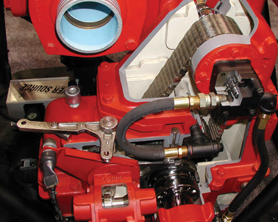
| PHOTO 1. Note switch activated by lever lower left hand. |
 |
|
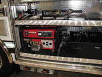
| PHOTO 2. Genset, door must be open and tray extended to allow operation. | |
 |
|
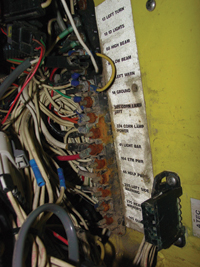
| PHOTO 3. Corroded electrical connections. | |
 |
|
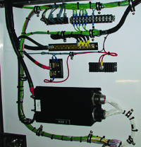
| PHOTO 4. A multiplex system, note the word NODE 2 on black box. | |
 |
|
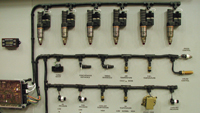
| PHOTO 5. Typical electronic multiplexed systems for a modern diesel engine. The injectors on the top row are outputs, the devices on the bottom two rows are inputs. | |
 |
|
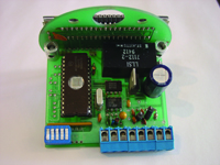
| PHOTO 6. Picture of rear of a typical pressure gauge showing five blue dip-switches. Photos by Don Henry |
The NFPA defines an interlock as a device or arrangement of devices in which the operation of one part or one mechanism of the device controls the operation of another part of another mechanism.
Many of the interlocks we will discuss here are required by NFPA 1901, but many manufacturers of high-quality fire apparatus use additional interlocks and therefore will exceed the standard to ensure safety.
Technicians must understand the reason and function for these interlocks.
Interlocks have been used in fire apparatus for many years. Some of these interlocks were as simple as the transmission neutral start switch, an electrical switch that would not let the engine in a truck with an automatic transmission start unless the transmission was in neutral. The switch was held in the open position until the transmission was put into neutral, The switch was then closed and a complete circuit made with the starter control circuit, meaning the engine could start if the key or start switch were closed on the dash.
A similar switch was used on trucks with manual transmissions but was activated by the application of the clutch pedal.
It was very important that the engine speed not be allowed to increase if the transmission was not in neutral, or, in the case of a standard split shaft fire pump, the mechanical connection to the wheels was not disconnected.
Without these interlocks, it would be possible for the apparatus to move as the engine throttle was advanced from the operator pump panel. This condition would put the driver-operator and everyone at a scene at great risk.
|
|
| VIEW LARGER
|
If the pump had been shifted successfully from road to pump and the transmission is in gear, then a throttle-ready indicator light on the dash should come on. The test for this interlock is simple; with the transmission in neutral and the parking brakes not set advance the speed of the engine from the pump operator’s position with the pump panel throttle. The pump panel throttle should not be able to change the engine speed. If the truck is equipped with a pump-and-roll feature, then the only throttle that would be operational would be inside the cab when the truck is in motion.
|
|
| VIEW LARGER
|
The fire pump is another matter. The amount of water that flows to the hoses from the pump and, therefore, to the firefighters, depends on the speed of the fire pump impellers, the inlet pressure, and the length and size of the hose. If the engine speed were to increase or decrease without the direct control of the pump operator, then the lives of the firefighters would be at great risk.
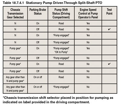
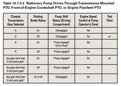
The NFPA has produced two tables that are helpful for identifying and diagnosing interlock problems. The NFPA has have given me permission to reproduce them here. This and other important information is contained in the NFPA 1911 Standard for the Inspection, Maintenance, Testing, and Retirement of In-Service Automotive Fire Apparatus. Make sure you have the 2007 copy as it contains not only 1911 but also now 1914 and the very important out-of-service criteria that was in the 1915. You need a current copy. The first time the need for interlocks appeared in the NFPA 1901 was 1991, that’s 19 years ago. Please take the time to ensure that your interlocks are working.
Back to the fire pump. An interlock is used here again to prevent the engine speed from changing. If the fire pump is engaged then the engine speed would not be able to change. Even if the engine throttle was advanced from inside the cab, the engine speed could be changed only from the pump panel. You should not be able to change this speed with the foot-feed throttle in the cab. While this standard requires testing of the interlock only in two configurations, the tables above show the combinations in which the chassis transmission gear, the parking brake, and the pump shift in the driving compartment can be arranged, and whether the engine-speed control should be adjustable at the pump operator’s panel when that combination exists.
The person testing the apparatus might wish to test whether the engine-speed control is or is not capable of being advanced, as shown for the other configuration shown in the table.
When the apparatus is equipped with an automatic chassis transmission, the water pump is driven by the chassis engine through the transmission’s main driveline, and the apparatus is to be used for stationary pumping only, an interlock system is to be provided to ensure that the pump-drive system components are engaged in the pumping mode of operation so that the pumping system can be operated from the pump operator’s position.
In this situation, additional interlocks were needed as more electrical accessories were added to the apparatus, such as increased lighting, radios, air conditioning and the ever-present problem of poor cooling due to lack of road draft. It was found that increasing the engine speed would solve some of these problems. For example an alternator’s output (amperage) is very low at engine idle; if the engine speed could be turned up to, say, 1200 to 1500 rpm from 700 rpm, then the alternator would function better.
This, of course, could not be allowed if the fire pump were also engaged. Some 110 to 220 volt generators can run only if the compartment they are in is opened to allow the correct circulation of air. This would be a use for an interlock to ensure that the compartment was open and the generator tray was in the fully slide-out position.
In the past, this was done with switches, electrical cable, relays and kilometres of wire.
Another interlock;
- If the cab has a powered tilting system, the system shall be interlocked to operate only when the parking brake is engaged and shall be configured so that the failure of a single component will not result in unintentional tilting of the cab.
- An interlock shall be provided to prevent operation of the equipment rack unless the apparatus parking brake has been activated.
These are just some of the interlocks there are more and many that are used on aerial apparatus.
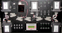 |
|
| Example of a multiplex system used in fire apparatus. Photo by Don Henry |
■ Enter multiplexing
The connecting of all of the electrical\electronic models, relays, inputs, outputs and computers is called multiplexing. In older apparatus a tremendous maze of wires controlled, powered and monitored the various electronic and electrical devices.
The cost to of materials and labour, simply wire an older truck was very high not to mention troubleshooting and repair. Multiplexing has removed kilometres of wire from the truck and made testing and troubleshooting much easier. On older trucks, each circuit had to have its own power wire, ground wire (at least to where it can corrode at the frame) and possibly a signal wire to turn on or off a relay. (See photo 3.) This consisted of hundreds of individual wires of different sizes and lengths. In many cases, these mulitiple wires have made it impossible to build or use a standard wiring harness, and, therefore, the costs of manufacturing went up. But what if you could have only one power wire and one ground wire to service the complete truck?
The power wire would be a 12-volt direct current power supply and also an alternating current signal. This AC signal would contain the information about what device to turn on or off and whether that device had functioned as it was instructed to.
This information, imposed along with the 12 DC power, would be a digital signal. This signal is called a protocol. There are many different protocols; some move information very fast, some slower. For example J 1939 is used to commutate among the engine, transmission and Electronic Control Units (ECU). J 1922 is used to communicate between the engine and the antilock braking system (ABS). J1587 is used to communicate the engine, ABS, multiplexing of the ECUs with the data-link reader devices suck as a PRO-LINK or a laptop computer.
As the data link for the PRO-LINK does not have to update itself as often as the engine has to communicate with, say, the ABS system, this is much slower protocol.
The Society of Automotive Engineers sets the parameters and speeds (baud rate) for these different protocols. Note that this is not a new idea: in fact, one of the earliest protocols to use a digital signal (on-off) was Morse code. It was, of course, a very slow data rate. Now we have these very fast signals imposed on top of the DC power source or travelling in separate wires called a CAN DATA BUS. CAN stands for Controller Area Network. Many Data Bus wires are, in fact, two wires. These wires are twisted around each other about every couple of inches. This twisting help to reduce unwanted electrical interference; these wires are often called a twisted pair. This data (protocols) is sent from the computer to a device called a module or a node. These modules connect with the other electrical devices on the truck and – this is also called interfacing – and it allows the electronic signal to control an electrical device.
So, let’s look at very simple circuit. You want to turn on the left-hand signal lights. In the cab, the driver will move the left-hand signal turn lever. This is a digital device – a simple on-off switch – and is called an input. This signal would then travel to a module – often called a vehicle interface module (VIM). From there a signal (protocol) would travel in the wire; it may go to dozens of different devices ether in a data bus or embedded in the 12v DC power wire but as part of the protocol there will be an address. This address will only activate the left-hand front and back signal lights plus any required side makers. The right-hand marker will simply ignore the signals.
At one time this addressing business was done by setting small dip switches on the device similar to the method you may have used when you set up you garage door opener. One method used now is to connect your laptop to your fire truck and, with the correct software, change the address electronically. But, how can hundreds of different signals travel in the same wire at one time? Think of the satellite TV in your house. You many get 250 or more different channels but there is only one cable coming into your house. In this cable, there are 15 volts going from your satellite receiver in your house to the feed-horn amplifier in the center of your satellite dish, and at the same time hundreds of TV program signals are traveling in the opposite direction, from your dish to the receiver in your house. You can now see that many different signals can be carried in the same wire at the same time.
With the advances in electronic and computer controls, it is now possible to write software to improve both the safety and functionally of new apparatus. This can be done with inputs and outputs. Or, I\O. Inputs can be ether analog or digital signals. An example of an analog signal would be the output from a wheel (ABS), shaft speed sensor (rpm) or a throttle position sensor (foot feed for the engine throttle).
An example of a digital signal is not as complicated as it sounds. It can be as simple as an on-off signal such as a pressure switch in the Allison C3 clutch, or a door open switch. This on-off signal is also called a discrete signal by many manufactures.
After the computer receives this input information it can process it and compare it to the parameters that are part of its software package. Does it have the software of a fire truck, or a refuse truck? This is also referred to as personality.
The computer will then turn on or off certain functions; this signal to perform a function is called an output. Here is just one example. If the driver or passenger seat senses that a weight is placed on it, this would be an input. At the same time, the computer is looking for the signal that the correct seat belt should have been done up – another input.
If the seat signal is present but the seatbelt signal is not, then the computer will not allow the transmission to be placed in a gear. That’s an output.
You need to understand that computers don’t really think – they just react. When given a certain set of inputs, computers will then control a certain set of outputs to conform to the software that has been programmed into the computer.
Computers by themselves can directly control only a small amount of current through the use of transistors; a transistor that can handle a large amount of current is often called a driver. Even a large transistor will not normally handle more than five to 10 amps of current directly. You should never use a test light to probe a wire to check for electrical power. First, many times the maximum voltage will be between one and five volts, so a standard 12-volt test light would not ever light up. But, more important than that, the standard test light could draw as much as one amp or more. One amp does not sound like a lot of current but many transistors can handle only 20 milliamps (1⁄20 of an amp). This current draw will cause the transistor to go open (burn out) and, in many cases, it is not possible to replace just the one blown transistor in the computer or module and the cost could easily be thousands of dollars. So, it will be necessary for the transistor to control a relay. Relays are used to control such large loads as lights, air conditioning pumps, hydraulic pump controls or power take offs.
Some manufacturers encourage and challenge fire departments to approach them with new interlocks, not only the NFPA requirements but new innovative uses of this technology. A true genius in this field is a friend and fellow member of the Apparatus Maintenance Section of the IAFC, Bob Neitzel from the Navistar. It is truly refreshing to meet people who say yes we can, not go away and leave us alone.
Don Henry teaches the Automotive Services Technician and Heavy Equipment Technician programs at Lakeland College in Vermilion, Alta. He can be reached at don.henry@lakelandcollege.ca
Print this page