Equipment
Truck Tech: November 2011
So, fall is upon us, hockey is on TV and, WAIT . . . wrong magazine.
November 14, 2011
By Chris Dennis
So, fall is upon us, hockey is on TV and, WAIT . . . wrong magazine.
Now that I am back on track, we can talk about fire pumps. We are going to go over fire-truck pump maintenance and knowing the importance of the ULC plate.
 |
|
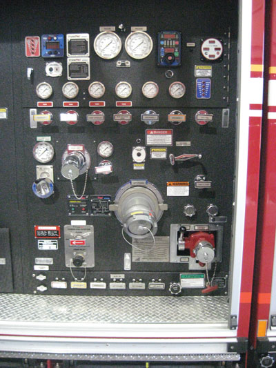
| Photo 1: Your department may specify differently, but keep this easy rule in mind when trying to navigate a truck’s pump panel: anything below the master intake port or steamer is an intake, and anything above is a discharge port. Pre-connects are a given. Photos by Chris Dennis |
A pump is a device used to move fluids. There are many forms of pumps. For our purposes, we will reference centrifugal pumps, the most common type of pump on commercial and custom fire trucks. Some examples of pump builders are Waterous, Darley and Hale. The concept is simple . . . water goes in one end and out the other.
The definition of a centrifugal pump (by Wikipedia) is a rotodynamic pump that uses a rotating impeller to create flow by the addition of kinetic energy to a fluid.
Centrifugal pumps are commonly used to move liquids through piping. The fluid enters the pump impeller (eye) along or near to the rotating axis and is accelerated by the impeller, flowing radically outward into a diffuser or volute chamber, from where it exits into the downstream piping (discharge). Centrifugal pumps are used for large discharge through smaller areas.
They are generally driven by an internal combustion engine or electric motor.
 |
|
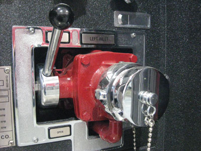
| Photo 2: Clean the threaded areas of the intake with liquid soap. Soap will lubricate the ball bearings inside the swivel, flushing and washing away dirt. |
Centrifugal pumps can consist of more than one impeller in a casing. Every design has a specific purpose. The maintenance is virtually the same on a single impeller (single stage) as it is on two impellers (dual stage). If the water source with which you are working is static or pressurized, the pumps should be back-flushed after every event. At times, rural fire fighting requires firefighters to draw from streams, ponds or lakes – not exactly clean sources of water. You will encounter sediment, weeds, sand and anything else that grows or swims in one of these bodies of water. Back-flushing – flushing the pump, discharges and intakes, as well as removing any onboard water that may have been transferred into booster tanks – is a must. When you back-flush, you go from the highest discharge and push fresh water back through the pump to its intakes.
All screens and the steamer ports, if capped or equipped with master intake valves, must be removed or opened. This includes all smaller intakes as well. Once completed and reassembled, the fire pump can be engaged and fresh water can again run from intake to discharge. Back-flushing will dislodge any loose items that may have snuck past the screens and will move out any sand particles. Sand or sediment is a bad thing. Move enough high-pressure water and sand mix, and you will create an amazing cutting tool capable of going through steel and concrete. This would be great if that’s what you needed to do, but for our purposes, we only need to move water . . . quickly!
I mentioned earlier that the water enters the eye of the impeller and is moved outward at a high rate of speed through the impeller into the housing or volute. It is here that the shape of the pump housing changes and becomes smaller and narrower where the water is discharged out to piping. The impeller spins by an area in the housing called the stripper edge. This is the leading edge out to the discharge piping. If this stripper edge is degraded by sand blasting, the pump is no longer able to create the pressures or litres per minute for which it was first designed. We now have a fire pump that does not meet or pass a pump test.
A simple way to eliminate this early wear is to back-flush the pump every time it is used. Pressurized sources, such as fire hydrants, usually contain water from the city grid. This water is treated and is usually free of all pond stuff, but that doesn’t mean that these pumps are exempt from back-flushing. Steel pipes will cause sediment and rust, and the fire department is not the sole user of these hydrants. Anyone who has been there before has left some residue, which builds up over time and has to be cleaned out. Older townships may find that their hydrants are still supplied via clay pipes, which break down over time.
Fire pumps are equipped with intakes and discharge ports. The pump panel can be a very busy piece of real estate on a fire truck (see photo 1 on page 22). Your fire department may specify otherwise, but keep this simple rule in mind: anything below the master intake port or steamer is an intake. Anything above is a discharge port. Pre-connects are a given.
Each intake has a valve of some kind that opens and closes and is usually mounted close to the back side of the pump panel. The threaded areas of the intakes are a female coupling with a swivel. Use liquid soap to clean the threads. The soap will make its way into the swivel and will help to lubricate the ball bearings inside. This way, the water will always flush the swivel and help to wash away dirt (see photo 2 on page 22).
Lube with liquid detergent and the cycle continues. This also holds true for the internal function. Squirt small amounts of liquid detergent into the valve area to help wash away debris and to lubricate. If this is done after every event, or once a week during the operational pump test, these items will last a lot longer. Do the same to the discharges and they will not let you down when you are called to duty.
Mechanical relief valves
So now I am dating a few of us. Some readers may not be familiar with mechanical relief valves. Relief valves are used in most pumping systems to prevent excess pressures caused by changes in the conditions under which the system is operating. There are many kinds of relief valves and they function in different ways, depending on the type of pump, the characteristics of the pump driver (engine or motor, for example), and the operating conditions. Our relief valve is a pilot-operated valve used with a centrifugal pump driven by an engine or motor. Any or all discharge lines may be shut off without the knowledge of the pump operator (in other words, to relieve valves used on fire department pumpers). If we could not control pressure (pressure means net pump pressure, or the difference between discharge pressure and intake pressure), the end of the hose line not yet shut down would receive all the pressure built up in the system, creating an unsafe situation for the firefighter operating the hose.
 |
|
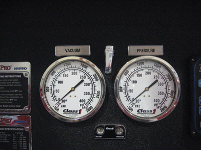
| Photo 3: A certified pump operator can check the pressures of the discharge master gauge to determine if the valve is working correctly. | |
 |
|
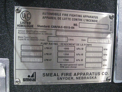
| Photo 4: The ULC plate, located on the pump panel, tells your fire department that the truck meets all Canadian standards and all the guidelines set out by NFPA 1901. Photos by Chris Dennis
|
The relief valve operation is the same no matter which brand of relief valve your department uses. One of the worst things firefighters can do is leave the valve in its last pre-set position. There is a spring inside, and if the value is left to sit in one spot too long, the spring will weaken and the valve will stick. The relief valve must be exercised, not only to see if the light works, but also to be sure it is operating properly. A certified pump operator will be able to determine if the valve is working correctly by checking the pressures on the discharge master gauge (see photo 3 on page 86).
If the open or closed bulbs were burned out, how would you know the relief valve is working? A veteran pump operator will tell you by the sound, but with all the noise from radio traffic and engines running, a visual inspection of the gauges will never let you down. Pump training for firefighters and technicians is important; it is not just putting the water on the fire – it is doing this safely and effectively without hurting firefighters or damaging equipment, and knowing if your fire pump is working to its potential. The relief valve needs to be exercised – fully open, fully closed, turned on and turned off, light bulbs on and off, screens removed and clean – so that when this safety item is required to do its job, there is no question that it’s going to work properly.
Electronic pressure governors (EPGs) have replaced mechanical relief valves. They do all the work for you. If hose-line pressures change unexpectedly, the EPG will communicate with the engine ECU (computer) by increasing or decreasing engine revolutions per minute. The only maintenance they require is making sure the engine monitoring functions and all related lights for interlocks work, as well as being able to switch from revolutions per minute (r.p.m.) to pressure modes.
If your pump is equipped with push/pull/open/close valves, hand-wheels open/close valves or electronic open/close valves, be sure they are always kept clean and free of dirt, especially with open or enclosed pump panels in the winter.
Pump panel and ULC plate
ULC plates are found on apparatuses with fire pumps and are located on the pump panel (see photo 4). The ULC plate is a certification that tells your fire department that the fire truck built by the vendor meets all Canadian standards and all the guidelines set out by NFPA 1901. This plate tells the pump operator what the fire pump was tested at from a draft at three metres of lift to achieve maximum flow rates at 100 per cent of the pump’s operating rated capacity.
The plate also lists the vehicle identification number, the inspection and compliance date, litres per minute (lpm), kilopascals (kPa), and the r.p.m. at which the engine operates.
The ULC plate has a set of constants on it: 1,000 kPa, 1,350 kPa and 1,700 kPa. These pressures do not change; they are the pressures at which the pump should be tested from a draft.
We’ll look at an 8,000-lpm centrifugal pump. At three metres of lift, this pump should produce 7,070 lpm at 1,000 kPa and 1,666 r.p.m. The next increment is 4,936 lpm at 1,350 kPa and 1,790 r.p.m.; and the last increment is 3,535 lpm at 1,700 kPa at 1,910 r.p.m. This information is based on actual pump numbers when it was tested.
I have seen many cases in which, when tested, the litres-per-minute value is a round number – not exact as this plate shows. This, too, is OK. The plate can help as the pump gets older. A pump operator can be the first line of defence for the repair technician. When flowing large amounts of water, the pump operator – using the ULC plate as a guideline – can tell if the engine is working harder to flow the same amounts of water. For example, this 7070-lpm pump is working at 1,000 kPa at 1,666 r.p.m. It has worked this well for some time. Then, the pump operator notices that the engine r.p.m. are running much higher in order to produce the same litres per minute at 1,000 kPa. This information can be forwarded through the chain of command and dealt with long before a failure occurs.
The ULC plate is also a guideline for pump testing. When testing is done and the fire pump fails (as it will not reach the numbers to which it was specified and built), a couple of things can be done. The pump can be repaired as needed. If all that’s required is a pump packing or a valve, then economically, it is better to repair. If internal functions are worn out and not critical, the pump can be re-rated and the ULC plate can be re-issued with new ratings. The new ratings will vary with each department and their needs.
I have determined over the years that the pumps are not always to blame. In some cases, pump operators need to be re-educated. As technology changes, training divisions must adapt to provide pertinent and current training. Firefighters train to the max when a new automotive extrication technique comes about, or a new tool is purchased to make the job quicker, safer and more effective. That same standard should be applied to pump operation. When a new truck goes into service, every platoon is trained on the apparatus and its functions. There is nothing the driver or pump operator (engineer) has not been trained on. To stay current and effective on fire pumps, some general preventive maintenance will keep our staff safe, our community well protected and our equipment on the road longer.
Check back in December for my column on aerial preventive maintenance for everyone from the front-line firefighter to the front-line emergency vehicle technician.
Chris Dennis is the chief mechanical officer for Vaughan Fire & Rescue Service in Ontario. Contact him at Chris.Dennis@vaughan.ca
Print this page