Equipment
Truck Tech: November 2014
Air brakes are typically found on heavy trucks, trailers and buses and are made up of several components which, when assembled, work together. It’s important for function and safety to correctly and frequently maintain the air-brake systems on our fire trucks.
Every airbrake system includes service brakes, parking brakes, a brake pedal, an air compressor and air tanks. The system needs a supply of air created by the air compressor, which can either be remote-mounted and belt-driven off the engine’s front pulley system, or bolted down onto the engine and driven directly off a set of gears located at the back or font of the engine, depending on the engine make and application.
The compressor supplies air to storage tanks to be used by the control system; this is the working side of the brake. The compressor also sends air to the auxiliary air system – an NFPA requirement based on the fact that air horns use large volumes of air. If this system were not in place, the control system would quickly be out of air.
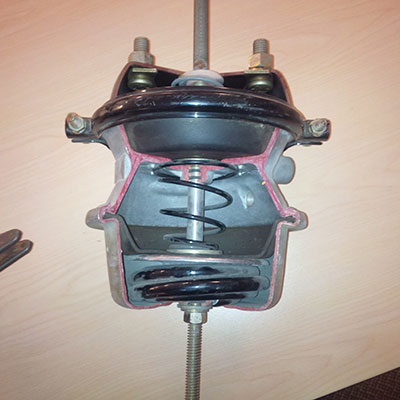 |
| Photo 1: A parking brake, shown released with the heavy spring collapsed, is controlled using air pressure. |
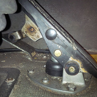 |
| Photo 2: A service brake is controlled with foot pressure applied to the pedal brake, shown, to slow the vehicle and bring it to a stop. |
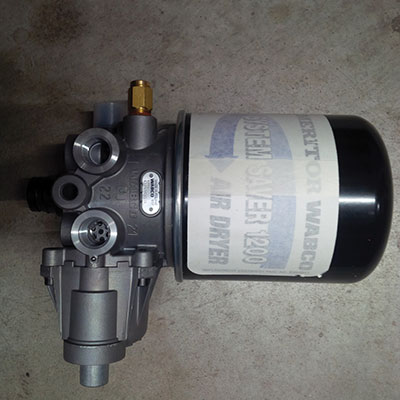 |
| Photo 3: A common air dryer removes moisture and oil impurities in the compressed air used for the airbrake system. |
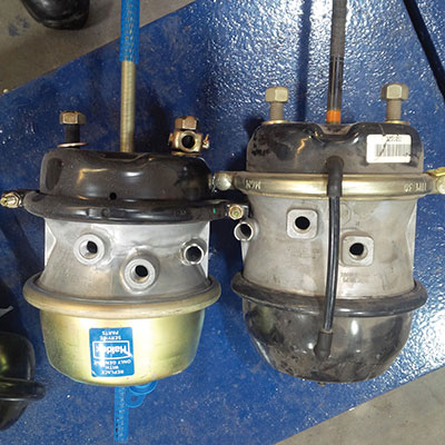 |
| Photo 4: Brake chambers are made of different sizes. The size determines the correct brake stroke adjustment for long-stroke and short-stroke chambers. Photos by Chris Dennis |
The service brakes are the ones the driver activates with foot pressure applied to the brake pedal. This action slows the vehicle and eventually stops it (see photo 2). Today’s air-brake system works between 100 and 130 pounds per square inch (690-896 kilopascals). This is the amount or air pressure built up by the air compressor.
The air compressor (see photo 3) is driven by the engine, either by crankshaft pulley via a belt or directly from the engine’s timing gears. The compressor is lubricated and cooled by the engine’s lubrication and cooling systems. Compressed air is created in the compressor then sent to the air dryer where moisture and oil impurities are removed. The air dryer may include a safety valve and a smaller purge reservoir (see photo 4).
The compressed air is then moved from the dryer to a reservoir called the wet tank. From this tank the air is distributed through a four-way protection valve into the front and rear brake-circuit air tanks, the parking-brake tank, and the auxiliary air-supply tank.
The control system is further divided into two service-brake circuits: the parking-brake circuit and (if equipped) the truck and trailer-brake circuit. This dual-brake circuit is further split into front- and rear-wheel circuits, which receive compressed air from their individual reservoirs for added safety in case of an air leak. The service brakes are applied by means of a brake-pedal air valve that regulates both circuits. The parking brake is an air-operated spring brake, applied by spring force in the spring-brake cylinder and released by compressed air via a hand-control valve.
All fire-truck drivers must be certified by their provincial departments of motor vehicles. This certification means the driver completed a written and practical driving test and should know the names of parts, what they look like and how they work. Every province provides a driver’s handbook on air brakes, available through the local motor-vehicle licensing office or on the Internet. Be sure the Internet version is specific to your province.
I have worked with many volunteer departments on driver training and I have noticed that not all departments complete hands-on brake checks. Oftentimes, circle checks are done and equipment is checked regularly, but not all departments have their drivers complete brake-adjustment checks. Doing these checks does not mean a driver must adjust the brakes each time; it means he or she completes a visual inspection to make sure the brakes are adjusted correctly for the brake system on each truck. It also means identifying brake-chamber sizes, long- or short-stroke chambers, auto or manual slack adjusters, and learning how to complete a brake stroke check.
A department may have a licenced truck technician come in once a month to complete this inspection as well, and perform preventative maintenance adjustments as needed. A department may also train all its drivers how to inspect and complete a mark and measure of brake stroke. I will be blunt and I mean no disrespect: if your department is doing a mark and measure inspection (hands-on), well done. How else, as a driver, are you going to know if the brakes are adjusted properly or if they were broken the last time the truck was out? If you’re not checking for adjustments, at least post-trip, then how will you know if the truck is safe to drive next time? There are brake-adjustment indicators that can be installed to give the driver a visual check and determine if brake stroke is correct. Again, if the driver cannot mark and measure as well as see the installed visual indicators, how will he or she know they are in adjustment? In my opinion, if the driver is certified to drive with airbrakes, he or she has to know how to mark and measure. Give drivers the tools and knowledge to know that, with the licences they hold, they must be able to know what is happening – not as a mechanic, but as a certified driver.
Brake chambers are made in different sizes and the size is what signifies the correct brake-stroke adjustment (see photo 5). The top chamber is long stroke; you can see the square shape where the airline would go in. The bottom chamber is short stroke; the shape where the airline goes in is round.
The following information is a condensed version of a Vaughan Fire & Rescue Service lesson plan.
The type of brake chamber, in terms of its size, is determined by using a caliper or a tool (a Chamber Mate, for example) to measure the outside diameter. The type of brake chamber, in terms of its stroke, is determined by looking for visual identifiers. The absence of a recognizable long-stroke marking requires the inspector to deem the brake chamber to be a standard type – or short-stroke chamber – and not a long-stroke type.
All stroke markings placed on a brake chamber by the manufacturer refer to the rated stroke of the chamber. Rated stroke is a design feature and is generally one-half inch (13 millimetres) greater than the brake-adjustment limit of a chamber.
There are three different methods for identifying long-stroke brake chambers. Many chambers use all three of these identifiers, but just two of the three are required. Look carefully, though, as it is always possible that one or more of these identification tags has detached from the chamber.
1. Service instructions embossed or stamped onto the chamber.
Identification and service data: many long-stroke brake chambers have identification and service data stamped, cast or embossed onto the metal parts of a brake chamber. Others are provided with an adhesive data label. The data provided often identifies the type of brake chamber and may also include the rated stroke. For example the letter L and LS following the size (12 through 30) are often (but not always) used to identify long-stroke chambers. Other alpha-numeric codes are also used to identify chamber type.
2. Tags showing the rated stroke of the chamber. These tags are trapezoid-shaped with information embossed on the surface.
Many manufacturers of long-stroke chambers identify them by installing a tag in the shape of a trapezoid that shows the rated stroke for the chamber. These tags can be any colour and be made of any suitable material; they are usually installed near the air fitting or a clamp bolt. Information listed on the tag may also be repeated on the chamber itself.
3. Square-shaped air ports or a square-shaped embossment around the air port.
Most long-stroke brake chamber manufacturers identify the chamber by using square-shaped ports where the air fittings connect, or emboss the pressure cap section of the chamber housing with a square shape. In many cases the square shape has rounded corners. Any indication of the square shape is an acceptable identifier of a long-stroke chamber.
Note that there are two sizes of type-20 and type-24 these two long-stroke chambers and the rated stroke for these chambers can be either 2.5 inches or three inches. Confirm that the chamber is correctly identified.
Whenever the square embossment is 0.5 inches high, it indicates a stroke of three inches, having a brake-adjustment limit of 2.5 inches.
Some methods are not accepted as identifiers of long-stroke brake chambers.
The measurement of the thickness of the chamber cannot be used to identify a long-stroke chamber.
The interior design of the chamber differs among manufacturers. Exterior brake-chamber dimensions do not reliably identify the rated stroke. Rated strokes can even differ between chambers with similar exterior dimensions from the same manufacturer.
A square hole at the point at which the pushrod enters the brake chamber is not an indicator of a long-stroke brake chamber. The hole is sometimes square in order to allow the pushrod yoke to pass through the housing.
The colour of the trapezoidal tag does not indicate a particular rated stroke.
We must ensure that what we are measuring is correct. If our brake chambers do not match up, we risk improper adjustment, and, given the right circumstances, the brakes will not react correctly.
Chris Dennis is the chief mechanical officer for Vaughan Fire & Rescue Services in Ontario. He can be reached at Chris.Dennis@vaughan.ca
November 3, 2014
By Chris Dennis
Print this page